Subsurface Risk Engineering: GPR Survey for Voids, Mine Workings & Ground Instability
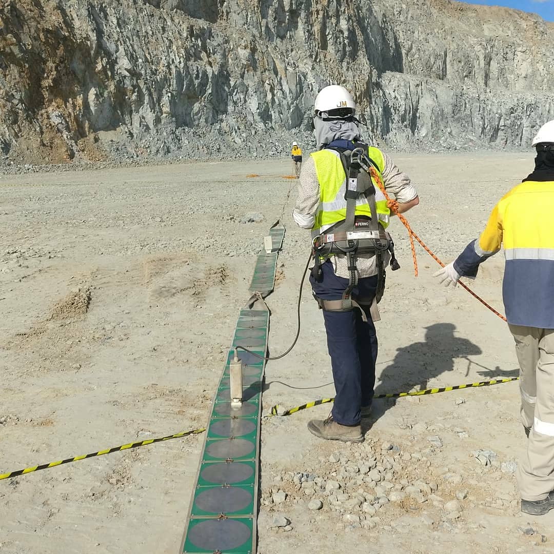
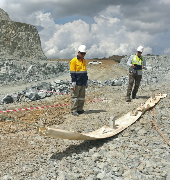
We use the Loza electromagnetic survey system to locate what creates risk before it becomes a failure: hidden voids, karst cavities, abandoned mine workings, seepage channels, and weak zones causing subsidence and sinkholes.
Void & cavity mapping: karst, solution pipes, washed zones, air-filled voids
Abandoned mine workings: stopes, shafts, chambers — including those absent from old plans
Subsidence & sinkhole risk: settlement, differential compression above disturbed ground
Infrastructure corridors: roads, pipelines, construction sites — paleorelief traps and weak soil lenses
Fault & fracture structures: discontinuities, groundwater discharge pathways
Dam & embankment integrity: seepage, suffosion, internal erosion, piping channels
How subsurface failures develop — and where GPR intercepts the process
Leakage / Infiltration
→
Suffosion / Soil washing
→
Void / Loose zone
→
Settlement
→
Collapse / Failure
Ground penetrating radar detects the process at the leakage → suffosion → void stage — when remediation costs are a fraction of post-collapse repair. We have surveyed infrastructure across 63 countries in Africa, Asia, Europe, and South America.
Survey deliverables (decision-ready output)
Risk zoning map: where to investigate, reinforce, or avoid
Depth profiles tied to the engineering task — not raw radargrams
Void geometry and depth estimates within site conditions
Priority drilling recommendations: where to verify first
Correlation with existing geology, boreholes, and project constraints
2D conductivity and permeability proxy sections for fluid and void discrimination
Targets
- Karst & cavities
- Stopes & shafts
- Faults & fractures
- Paleochannels / buried ravines
- Dams & embankments
Risks
- Subsidence / sinkholes
- Internal erosion / piping
- Leakage & saturation
- Slope instability
- Infrastructure damage
Actions
- Reinforcement / grouting
- Drainage & water control
- Route adjustment
- Targeted drilling
- Monitoring plan
Why our surveys reach what others miss
Most geophysical services for engineering tasks are limited to shallow investigation depths — sufficient for utility mapping, but not for detecting buried mine workings, deep karst cavities, or seepage zones in dam foundations. The Loza electromagnetic system operates at dipole frequencies down to 25 MHz, providing investigation depth sufficient for the geotechnical targets that actually matter: abandoned stopes, deep suffosion channels, bedrock faults below fill.
The system records the full electromagnetic response — structural and conductive — in a single survey pass. This means voids, fluid pathways, and weak zones are resolved simultaneously, without requiring separate surveys or method combinations.
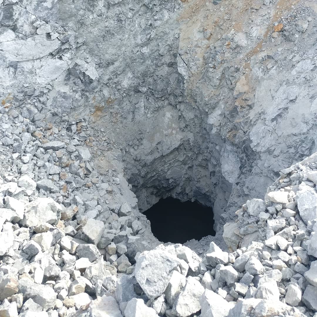
Abandoned Mine Workings Detection: Stopes, Shafts & Chambers
Abandoned vertical workings are among the most dangerous geotechnical hazards. They are frequently absent from historical mine plans — and surface collapse typically occurs without warning, often under roads, buildings, or active mine infrastructure.
The Loza electromagnetic system is particularly effective for detecting large-form voids, backfilled stope zones, disturbed crown pillar areas, and high-risk collapse zones before you place heavy infrastructure or commission ground-level operations above them.
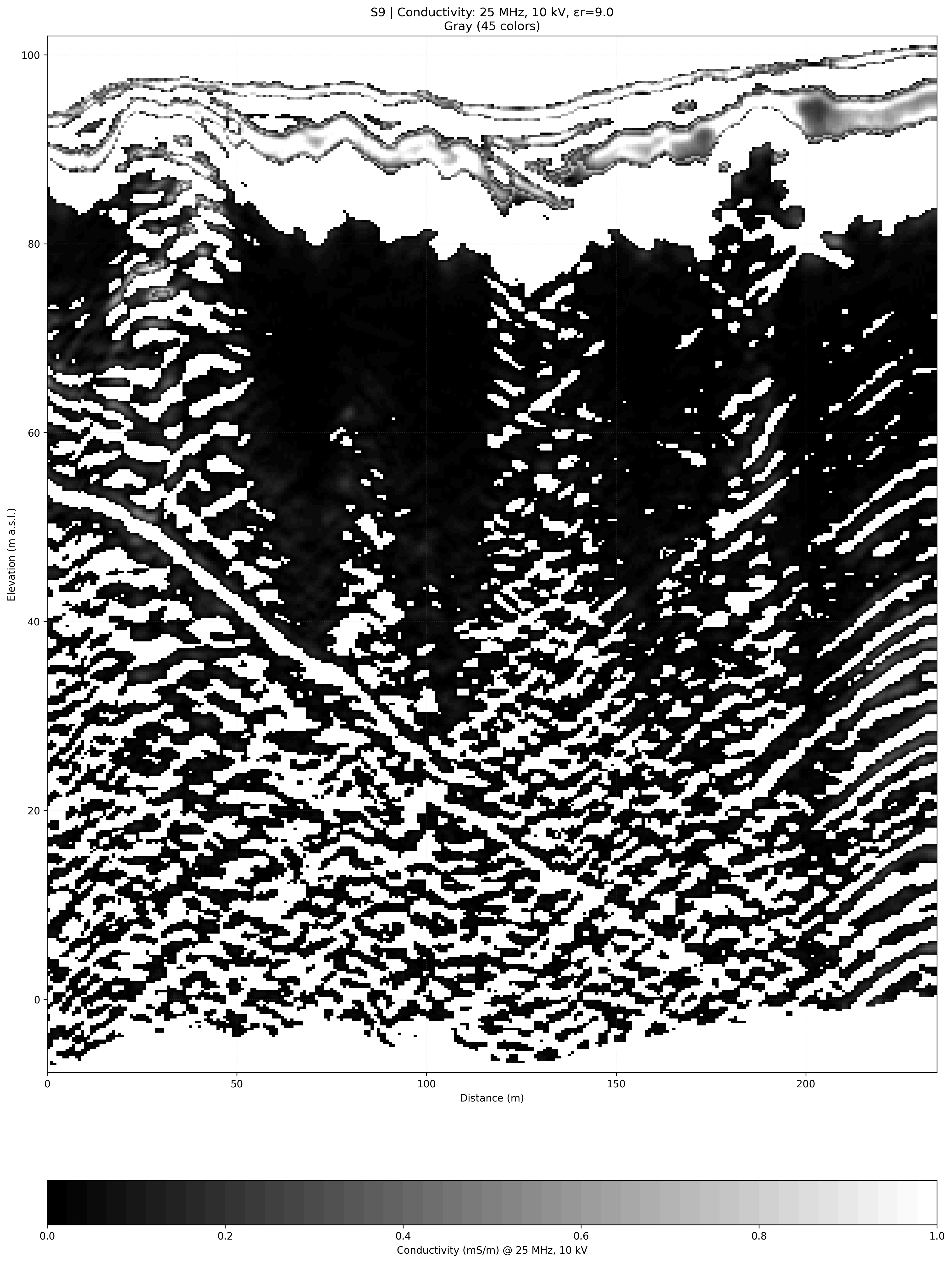
Kryvyi Rih, Ukraine — 2021
Stope and disturbed zone mapping
Work Examples: Underground Utility Detection & Pipe Mapping
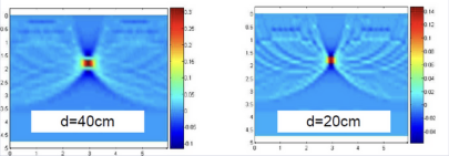
GPR detection of underground communications and buried pipes
Resolution across different pipe diameters
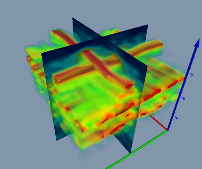
Pipe identification and lateral tracing

3D section — pipe cluster localization
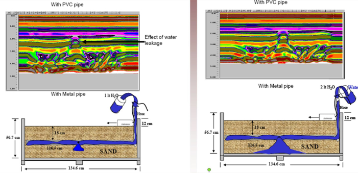
Water leak detection in buried pipes
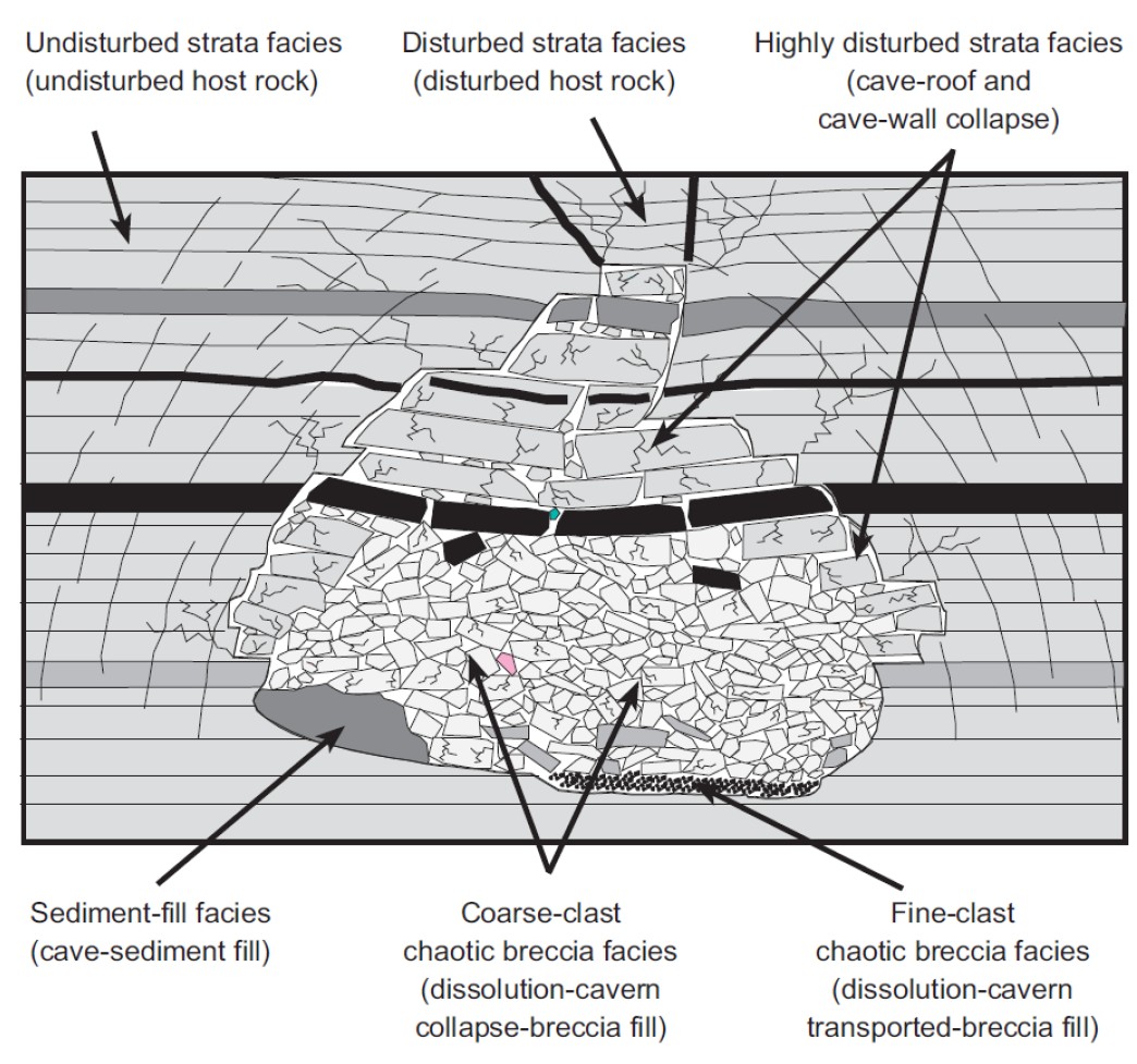
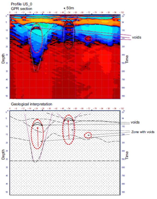
Karst Cavity Detection and Sinkhole Risk Mapping
Karst is a progressive failure mechanism: dissolution opens cavities, weakens the rock roof, and generates sudden sinkhole collapse without surface precursors. The Loza system resolves cavity geometry, roof thickness, and infill state (air-filled vs. water-saturated) — the distinction that determines whether remediation is possible or urgent.
Karst sinkhole collapse — surface expression
GPR radargram — karst cavity detection
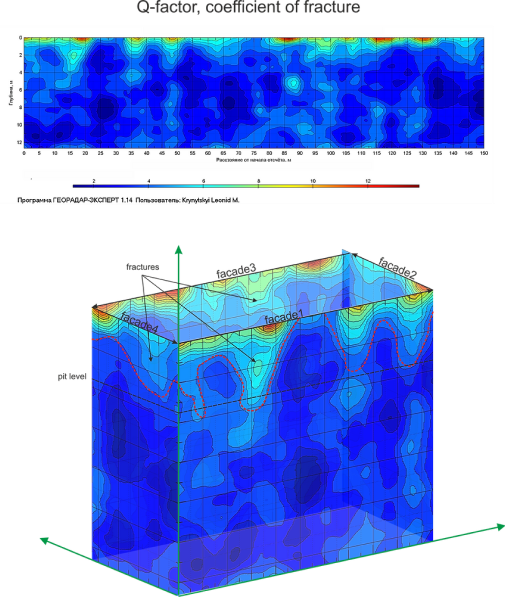
GPR Analysis of Building Foundations and Subslab Voids
Foundation GPR survey identified zones of active infiltration, fracturing, and preferential groundwater flow pathways beneath the building footprint. Risk zoning allowed targeted remediation — without full excavation.
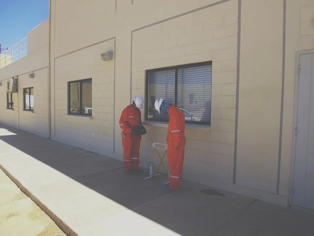
Problem zones in office building foundation
Infrastructure Corridor Surveys: Roads, Pipelines, Linear Projects
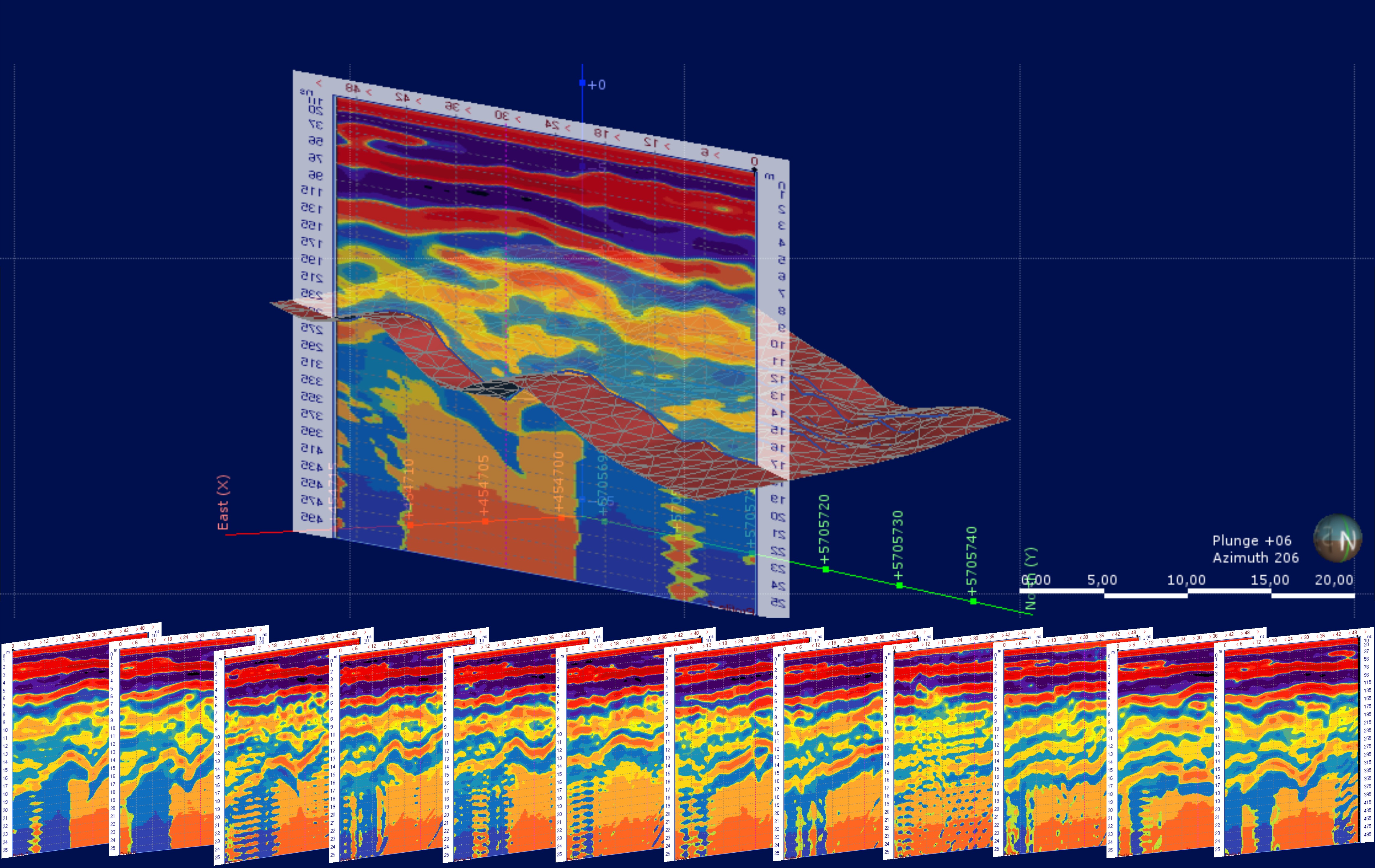
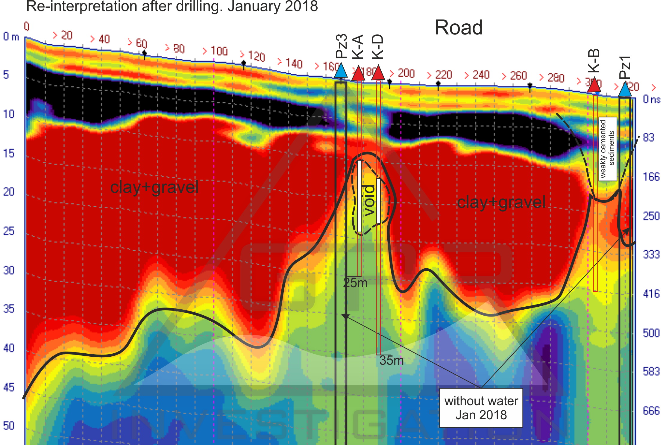
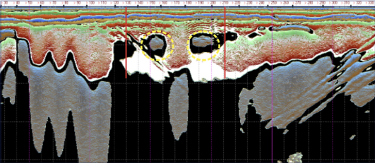
Buried paleorelief is a systematic trap for linear infrastructure: old channels, hidden ravines, saturated lenses, and compressible peat layers that re-activate under load and generate differential settlement. GPR corridor mapping at 200–500 m/day covers alignments efficiently and flags risk zones before construction decisions are locked in.
Pipeline route — GPR geotechnical survey
Bedrock depth mapping, soil quality assessment, and integrity evaluation
along the pipeline corridor.
1. Pre-construction risk reduction.
2. Informed route and design decisions.
Road corridor — sinkhole and weak zone detection
Dam and Embankment Inspection: Seepage, Piping & Internal Erosion
Dam failures follow a predictable sequence: leakage → suffosion → piping channel → void → breach. The Loza system resolves this process at the seepage and early suffosion stage — when intervention cost is 1–2% of a post-failure remediation.
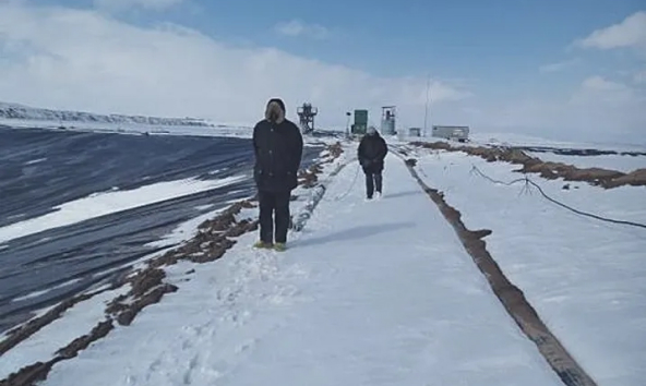
Seepage zone detection in earthfill dam
Loza-2N system, 6 m antenna (25 MHz). Fill thickness surveyed: up to 20 m. Leakage zones identified at 155 m and 180–200 m along dam axis.
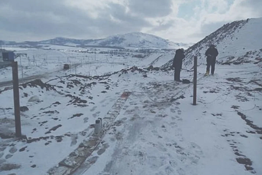
Dam body inspection — Far East, Ukraine
Internal erosion — structural damage zones
Dam survey — Kazakhstan
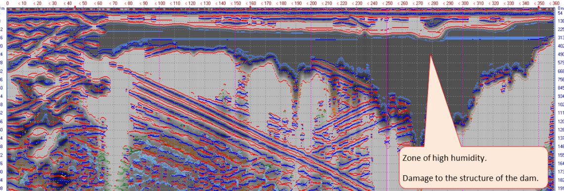
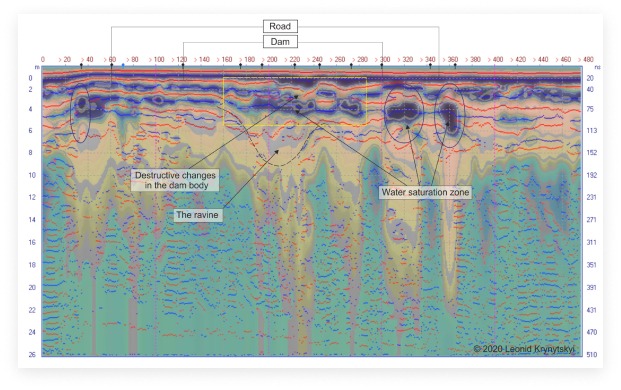
Fault structures and heterogeneity in dam body
Survey resolved fault-type discontinuities and significant material heterogeneity
in the dam body — including zones of elevated seepage risk.
Loza-2N system, 6 m antenna (25 MHz).
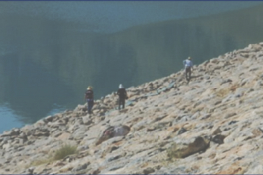
Dam inspection — Kryvyi Rih, 2020
Underwater GPR: Bathymetry, Sediment Profiling & Bedrock Mapping
Subsurface mapping through water — application areas:
Freshwater lakes and reservoirs
Rivers and water courses
Reservoir sedimentation surveys
Tailings pond bottom profiling
Subsurface parameters resolved:
Bedrock surface depth and morphology
Stratigraphic boundaries in sediment column
Sediment type and compaction state
Contamination layers (fuel oil, heavy sediments)
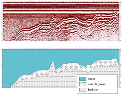
Through-water GPR — lake bottom survey
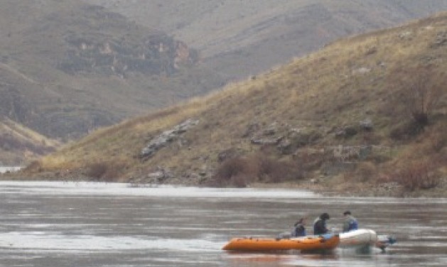
Through-water GPR operation:
Lake bottom sediment mapping, bedrock depth
Loza-2N, 3 m antenna (50 MHz)
Turkey — reservoir sediment survey
GPR survey for fuel oil contamination — lake bottom mapping
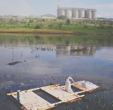
To assess fuel oil volume at the lake bottom, GPR soundings were conducted from the water surface. The Loza system was insulated from contamination and operated on foam floats, dragged from shore to shore at 1 measurement/second. Survey resolved heavy fuel oil deposits of 1.5–5 m thickness filling bottom depressions.
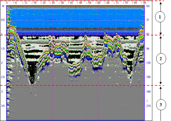
1. Water
2. Bottom depression filled with heavy fuel oil deposits
3. Clay substrate